Replacing A Intermatic
Mechanical Time Switch

This is a quick walkthrough of replacing an Intermatic Mechanical TimeSwitch T104M 220v version written by www.WCPandS.com. The steps for replacing an 110v version is almost
the same; they key is to reattach the wires you remove from the old clock with
the same slot position on the new clock.
Note: This only applies to replacing an Intermatic timer with
another Intermatic timer. Other brands are not covered.
Click on any image to see a larger version.
Click on any image to see a larger version.
In this specific case, an Intermatic T20001R box was used.

The much more common box is the smaller 2T511GA or indoor version 2T204GA shown below.

The much more common box is the smaller 2T511GA or indoor version 2T204GA shown below.

Starting
The first step is to turn off the breakers for the swimming pool
equipment. It is best to turn off all of the pool breakers at the house power
panel (breaker box).
Note: If you are unsure about turning off breakers, do not proceed
any further and seek a local professional for help.
Removing the panel
If you have one of the smaller boxes (2T511GA or 2T204GA), there will
be no panel to remove so you can skip to the next step.
For the larger T20001R version, as in this example, the front panel
needs to be removed before the time clock can be accessed.
There is a single hex head screw near the top that is securing the
front panel. Remove this with either a hex head or a flat head screwdriver.

The panel can now be removed by pulling the top section forward
(towards you), then up and out of the box.

(In this example, a light switch was attached to the panel so the panel
could not be completely removed.)
Removing the old time clock
Note: If you are unsure if the power is off do not proceed any further and seek a local professional for help.
Note: If you are unsure if the power is off do not proceed any further and seek a local professional for help.
There should be one or more flat head (or hex head) screws holding the time clock to
the box in position. However, it is possible that these screws were not used
and are missing.
Remove any flat head screws from the front of the time clock.

or

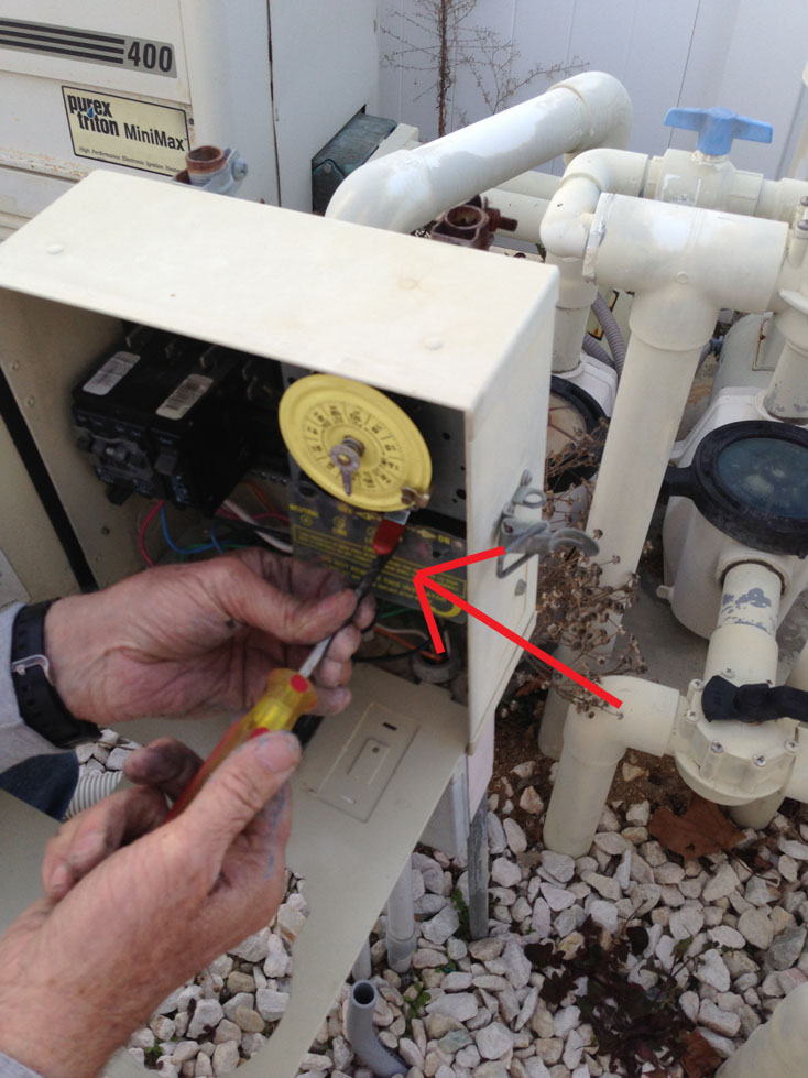
There is a clip on in the top left position of the time clock that
needs to be pushed up while pulling the time clock forward to free the it from
the panel.

There should be a plastic cover over the electrical wires; remove this
cover by pulling the bottom right side forward, then pushing the side that
pulled out down and out of the way.
Note: This cover could be missing. In this case, a new cover will be
in the box with the new time clock can be used with the new time clock.
Removing and attaching the
wires:
It is recommend to take a picture of the wires at the bottom of the old
time clock before proceeding any further. The wires will need to go back in the
new time clock in this exact position (Yours will very).

At the bottom of the time clock (new and old) are five Phillips head
screws with a small metal plate behind each that will hold the power wires in
place. When one of the screws is loosened, a wire can be pushed between the
plate and the time clock. As the Phillips head screw is tightened, it will
compress the plate to time clock holding in the wire.

Notice that when two wires are connected to the same slot, one wire
goes on each side (left and right) of the screw. This is important for properly
securing the wires and ensuring both are making the proper contact.

The best way to move wires is as the wires from the old time clock are
removed one slot at a time to immediately move the wire(s) to the new time
clock in the same equivalent position.


Putting the time clock back in
Once all of the wires have been moved from the old time clock to the
new, the new time clock will need
to be push back in to the controller box as the old was.
In the box for the new time clock, there should be a plastic cover for
the exposed wires and a set of on/off dogs. Place
the plastic covering on and over the exposed wires.

(The new cover may be clear like the above or a solid black)
Place the front panel back in to the box, setting the bottom section in
first into the groves at the bottom of the box.
Push the top of the panel in and align it with the top screw hole for
the hex screw.

Note: In this specific case, the on/off switch was bent on the
original time clock to fit inside the box without hitting the front panel. The
new time clock also had to be manually bent for the front panel to fit properly.
(See pic below)

Reattach the top hex head screw.
Turn the swimming pool power breakers back to the “on” position.
Setting the time clock to the
correct time and on/off schedule
The arrow pointing down on the time clock face “points” to the current
time. The clock is adjusted by pulling the clock face forward (towards you) and
then turning it clockwise or counter clockwise
until the arrow points to the current correct time.


To set the on and off times, the on/off dogs will be secured around the
clock edges. As the clock turns clockwise, one of dogs will turn the power
switch on and the other off. Both are clearly marked.

The screws on the dogs will only need to be hand tight. Using a tool
could over tighten them, causing them to miss the leaver behind and not
triggering the power switch as the timer moves.
I like this blog because it has an instruction on how to place that intermatic mechanical time clock. It is not easy to do a swimming pool repair when you don't have a knowledge about it.
ReplyDeleteThere are various online sources to provide you informative details on this topic, but this is one is very helpful
ReplyDeletepool service clayton ca