This is a write-up on the Pentair Intellicomm 2 interface
adapter (Manufacturer’s part number 521109, and our part number COM-30-1109). Written
by Wine Country Pools and Supplies in Temecula Cailfornia.
This is not a how-to for installing a Intellicomm, this will
show how two units were installed by us in these two specific cases.
This will include pictures of two installations and comments
on two different automated controller systems. A Pentair IntelliFlo VS SVRS
pump was used in both cases. For the automated controllers a Jandy RS and
Hayward Goldline automated control system was used.

When installing a new variable speed pump into an existing
pool equipment setup with an automated controller, the new pump might not be compatible
with the existing controller. The old automated controllers can only send
simple on/off messages to equipment (usually power/ no power). The variable
speed pumps contain computers to control the motors and need a data signal to
tell them what to do. One fix is to use the Intellicomm 2 adaptor in between
the pump and controller. When the
controller wants to turn on the pump, it will send a standard on/off signal to
the Intellicomm, and the Intellicomm sends the translated data signal to the
pump to start the appropriate preprogrammed speed.
The Pentair Intellicomm 2 box contains the following items:
• Intellicomm II Interface Adapter
• Two mounting screws
• Mounting tape
• One Terminal Connector (RS-485 and Intellicomm II power
connection)
• Compool RJ12 Adapter
• Four AUX cables (22 AWG)
• Installation and User’s Guide

The first
installation was on a Jandy Aqualink RS Control System.


A cable was cut to use as the power cable from the RS to the
Intellicomm.

This cut cable is now wired to the Jandy RS red terminal power
bar. There were already 3 wires connected to this same connection and the Intellicomm
was added as the 4th item to be powered by the board.

Next the variable speed pump needs to be wired so it is always
on. The pump relay should be located, the pump removed, and then wired directly
into its breaker.

Using the data cable that came with the variable speed pump,
two wires from the pump go into the Intellicomm RS-485’s middle two
connections.

Now, using the cable that you cut for power (already connected
to the Jandy RS power terminal), connect this to the Intellicomm RS-485’s two
outer connections.

Connect program 1 from the Intellicomm to relay 1 in the
Jandy RS using one of the four AUX provided cables.

Do the same with program 2 and the next open relay on the
Jandy RS board.
The Intellicomm board can be mounted anywhere within the
Jandy RS box.
The second
installation was on a Hayward Goldline.
The setup is similar to the Jandy RS steps above, but there are
a few differences that will be highlighted below.
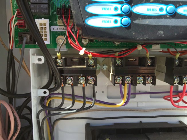
The picture below shows the inside of the Goldline with the
power terminal marked as “1” and the relay bar marked as “2”.

Connecting the power is the same process as above.

Since the relay bar is solid on the Hayward Goldline, then
the relay connected to it has to be altered to connect the Intellicomm.

The two screws holding the wire from the Goldline board
connecting to the relay need to be removed. Now two wires from the AUX cable
need to be cut, stripped, and connected to them.


For programming on and off times for either system, Set
timers for any relay connected to the Intellicomm for on/off times as if it
were a normal pump.
All speeds for each program are programmed on the pump itself
under “Ext Control”. In the “Ext Control” option there are 4 programs available.
Indian Massage in Bur Dubai
ReplyDeleteIndian Massage in Ajman
ReplyDelete