Saturday, May 24, 2014

Changing A Jandy Swimming Pool Light Bulb

This is a write up covering how we changed the light bulb on a Jandy pool light (Jandy part number WPHV500WS100, also known as Jandy Pro Series Large White Light) and a Jandy White small light. These are similar and the steps below will sometimes show both in the same steps for clarity.

Three of the largest swimming pool light manufacturers are Pentair, Hayward and Jandy. The process of changing a light bulb in a swimming pool/spa varies between these different manufacturers. We have a previous write-up on the Pentair Amerlites that can be found here

Most lights can be identified visually through the water without opening the light fixture. Jandy lights have a smooth rim with oval-shaped holes around the middle of the rim.

Starting:
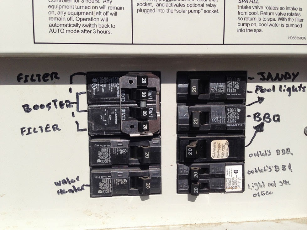
The breaker to the pool and spa lights needs to be turned off before doing anything with the lights.

To get access to the bulb, the light fixture needs to first be removed; this is held in with a single Phillips-head screw located at the top of the rim of the light.

Most fixtures can be removed by reaching into the water and removing this screw with just a screwdriver. In certain cases someone will need to get in the water to remove this screw.

If a spa is connected to a swimming pool (and higher than the pool), the spa can be drained into the pool using the filter pump to gain access to the spa light fixture.


Once the single top screw is removed, the light can be pulled out to either the pool deck or spa seat (if it’s the spa light).

Notice the sticker marking the top of the light fixture with the securing screw hole directly above it.
This will be important later when reassembling the fixture.

The Jandy lights use a plastic clamp assembly held down with 6 screws. These were removed with a Phillips-head screwdriver.


Once removed, the front steel face ring can be pulled off from the light fixture.


Clamp assembly removed from the fixture.


The lens can now be pulled away and off of the fixture. A flathead screwdriver was used in this specific case to wedge the lenses out of position.


(Pool)


(Spa)

The light bulb is now accessible and can be removed.

A standard 500W 120V swimming pool floodlight was used for the pool light.


 A 39W 120V medium base halogen light (part number PAR20) was used for the spa light.

Note: Once the new bulb is in, now is the time to test the new light bulb; however, only leave it on long enough to check if it comes on correctly or not. These lights are water-cooled and are not meant to be used out of the water for an extended period of time.

The lens gasket needs to be replaced whenever the light fixture is opened.
Pool light gasket part number: R0451101

Spa light gasket part number: R0400501

Note the two sides of the gasket. One side has a raised bump and the other is straight flat edge. The new gasket will need to be installed exactly like this one is shown here.

The old gasket can be pulled off of the lens.

Always replace the gasket.

The gasket has two sides: One has a straight edge.

The other side has a bump.

The new gasket is pulled over the edge of the lens. There is a raised bump on one side of the gasket; this should face back towards the light.


The lens and light fixture need to be pressed together. The top center screw hole on the outer steel face ring needs to line up with the top position of the fixture marked by the sticker around the outside.


Now the plastic clamp assembly needs to be lined up with the back of the fixture with the clamp opening at the top and held in position with the 6 original screws.

(Spa)


(Pool)

The fully assembled light fixture needs to be placed back into the pool/spa wall.
The extra cord can be wrapped around the light fixture and pushed into place with the top (noted by the screw hole on the face ring and sticker around the fixture base) up towards the sky as shown below.

A single screw is used to hold the fixture in place.


Note: Whether you are leaning over into the pool or completely in it, getting this screw into the correct position and started can be difficult. Patience is a virtue.


Tuesday, April 1, 2014

Piranha Power Pole Review

Update: See the 10 month update post here. 

This is a review of the Piranha Power Pole (Manufacture part number PP_LV made by the Smart! Company). Written by Wine Country Pools and Supplies.  Click on any image to see a larger version of it.

My first thought when seeing this pole was that it was designed to try to fix specific problems with most modern swimming pool poles, which is why I will compare this to a standard pole with normal wear after months of heavy use to show exactly what was being addressed with each change.

Below is a lineup of commonly found poles available for sale. The pole marked number 2 is a new version of the pole I used for comparison in this article; the Piranha Power Pole is marked as number 5. Both are 8ft closed and 16ft extended.

The new pole as it arrived. Comes with no paperwork but has a plastic bag cover, as seen below.

Starting at the far end of the pole with the red handle:
The first noticeable difference is that on most poles there is a twist lock so when the pole is extended this twist lock is turned (and therefore tightened) to lock the inner extension pole in place. Over time, as the lock wears with use, it will need to be tightened further and then further to keep the inner pole locked in place.

Note: On some poles this lock is on the end of the inner pole but has the same purpose.

On the Power Pole there is a lock that is set and released with a button on a red handle; the Smart Company calls this a “Lever Lock.”

When the button is pressed, the inner pole can be pulled in or out to change the overall length of the pole. On one side of the inner pole there are holes evenly spread out that are used to lock it into position once the button is released. The side with these holes on the pole is flat, and it is this non-cylinder shape that stops the inner pole from twisting independent of the outer pole.

This is a system I have not seen before on a cleaning pole, and on this new pole it works great. While fully extended, the inner pole is very stable. However, since this is new, I don’t know what will happen over time; I cannot accurately predict whether or not the locking system will remain as tight and stable as it is comes or if it will loosen over time.

The rubber handle on the end of the inner pole is slightly different.
On current poles the handle ends are not secured, and this allows it to move slightly up and down the pole that they are attached to. Over time the top breaks off as the handle is pulled down into the inner pole, as seen in the pictures below.


For the Piranha pole, the rubber handle appears to have been screwed into the inner pole.

This should stop the handles movement and prolong its use. Since this is new, I don’t know how this will wear over time with repeated use.

Now for the attachment end of the pole:
On standard cleaning poles on this end of the pole there are two holes that cleaning attachments connect to, which locks them in place.

Over time, the metal thins, eventually cracking with repeated use, as seen in the picture below.

Note: It is possible but difficult to repair a pole with this issue. If a few inches are cut off from just behind the cracked holes by using a saw, new holes can be drilled to connect the cleaning attachments to.

The Piranha Pole added two additional holes opposite the standard two that can be used to connect cleaning attachments to.

Note: There was a plastic insert inside the end of one of the two Piranha Power Poles we purchased. I don’t know if it was an adapter (for cleaning attachments with a thinner handle) or if they are even supposed to come with one attached. If they are then I don’t know why the other pole did not have one.

A closer view of the end with the open holes.

This should double the use life of the end of the pole since each set will get used about 50% of the time. However, since this is the first time I have seen this design, I don’t know if it will actually work out this way.

Final thoughts:
I can see how when designing the Piranha Power Pole the engineers were trying to fix specific issues with modern pool poles. The effort should be commended since so many other manufacturers are making so little advancement in swimming pool pole designs. But, at this moment, I cannot say if the Power Pole succeeded in everything it set out to do since a lot of what they did was for longevity reasons. For now, if you have a favorite cleaning pole brand/model, I would say stick to that. If you are looking for a new swimming pool pole, the Piranha Power Pole does a sufficient job and has no major drawbacks.


I will update this after at least six months or more of regular use and then I will have a better picture of how successful Piranha’s changes have been.  
Update: See the 10 month update post here. 

Sunday, March 9, 2014

Replacing Hayward H-Series Front Panel

This will cover replacing a Hayward H-Series front control bezel assembly (Manufacturer part number IDXL2BKP1930).

Note: This will not be a how to guide; instead it is a description of how we did this specific job. If you need to do any repairs on a swimming pool heater, always follow the instructions provided by the manufacturer.

Some heaters (Pentair, Raypak, and Jandy) have plastic UV shields that protect keypads and system LEDs from the elements; heaters that don’t (like the Hayward below) can suffer from weather damage, as shown in the pictures.


This H-Series heater in this article had a control panel that was so badly damaged the buttons stopped responding to touch.

The new panel, as seen below, has a circuit board connector cable connected to it. Once the cable is plugged in, any of the buttons pressed sends a signal to the circuit board. The lights and LED screen are part of the circuit board - not the replacement panel.


There are four Philips-head screws holding the old panel to the heater, so all four must be removed.

The panel can now be pulled forward away from the heater. A flathead screw driver can be used to pry the two apart.


The connecting ribbon must be pulled from the old front panel and out of the circuit board.

There are two Philips-head screws holding the circuit board to the old panel. These must be removed to separate the two.

The smaller green circuit board needs to be detached from the old front panel. There are just four plastic snaps holding it together. Push one side out, and then pull that half of the small board up and away to release it.

Here you can see the old panel next to the new replacement panel.

Note: The new replacement had two small pillars in the middle of each side that stopped new cover from sitting flat against the heater. I cut these off with wire cutters to make the new cover fit correctly. The newer models of H-Series heaters may have two additional screws to attach the panel to the heater.

The new panel was placed on the old circuit board, and then it was attached using the original Philips-head screws.

Now the LED screen on the small green circuit board needs to be pressed down and locked into position.

The new panel can now be pushed back into position on the front of the heater. The original four screws were then used to hold the new panel in place.

This specific H-Series heater had its LED display damaged while the circuit board was exposed to the elements. The old panel was so damaged that water could get into the heater and on the electronics. While the heater would work (heated water) in its current condition, the display is unreadable.

Supplemental pictures of changing an automatic water fill.

Supplemental pictures of changing an automatic water fill.
Here are a few additional pictures of a swimming pool automatic water fill being replaced. This is meant to be used for additional reference.
The original post with more detailed pictures is found here

A short video of the original water fill that is broke (it never stops adding water).

The original float still installed.

Two new auto fill floats, one of each size (3/8” and ½” ) next to the original float.

New float installed.


Tuesday, January 14, 2014

Spa Light Halogen Addendum

This is meant as an addendum to the previous Pool/Spa light bulb replacement write up. If your light does not look like the bulb in the example this article might apply to you.

Spa lights come in a few different forms: narrow flood, medium base halogen, a standard flood light or a thinner halogen JD bulb.

With any of the bulb types listed, the lens gasket is the same.

The installation difference is with the thinner halogen JD bulbs. Inside the light, after the lens and the lens gasket are removed, is a reflector.

At this point, the reflector can be pulled out.

Before a halogen bulb can be unscrewed, there is a metal brace that needs to be released by using one hand pull the two sides of the brace holding the bulb together.

While still holding the brace open, unscrew the halogen bulb.

When installing the new bulb, the brace will need to be held open. When finished, release the brace and it will hold the bulb in place.

Set the reflector back in the housing around the newly placed bulb.

Place the new lens gasket onto the old lens. The remaining steps are the same in the original write up found here
For reference the remaining photos of this specific job are below.


Friday, January 10, 2014

Swimming Pool Skimmer Equalizer/Float Assembly

Swimming Pool Skimmer Equalizer/Float Assembly
This article will explain what a Swimming Pool Skimmer Equalizer/Float Assembly is, how it works and what happens when one is missing.

Inside of swimming pool skimmers are either one or two open ports at the bottom.


Most modern pools have two with one connected to the system pump and the other utilized as an equalizer port. The equalizer port is connected to the main drain (at the bottom of the pool) or an open port on the side of the pool a few feet down from the skimmer opening. There is usually a float assembly unit covering both ports in the skimmer.

A float assembly is a saucer shaped device with a float inside and an adjusting flap on the bottom.

The flap is normally pushed to the side, leaving the center opening uncovered.

When everything is working properly and the water level of the swimming pool is at the correct level, water flows in from the upper opening down into the skimmer, through the float assembly and down into the back open port to the pool pump. See figure 1
(Figure 1)

If the water level drops below the skimmer opening, the float inside the float assembly drops which connects the equalizer and the pump ports. Water is pulled from the equalizer under the now closed float assembly and down into the pump port. See figure 2.
This ensures that the pool pump still circulates water, keeping the water filtering while cooling the pump motor (since it is water cooled).
(Figure 2)

The back port is used when connecting a vacuum hose to manually vacuum the pool. Not knowing what a float assembly does, it is common for swimming pool owners to remove these from skimmers and not replace them. Once removed, the system works as shown in figure 1. However, if the water level of the pool drops below the skimmer without a float assembly, the pump will pull air into the lines causing the system to lose prime (internal pressure pulling water from the pool and through the equipment). Most pool pumps cannot detect the loss of water flow and will continue to run dry. Since the pumps are water cooled, they can overheat, thus melting the connecting pipes and eventually burning out the motor.

If a swimming pool skimmer is missing a float assembly, these are not universally compatible and the makers name is needed to find the correct unit. To find the manufacturer’s name, check the skimmer lid to see which float assembly is needed. Some of the most common manufactures are Anthony Pools, American Products, StaRite, Pentair and Hayward Pool Products.