Thursday, December 11, 2014

Changing Turbine and Flaps on a Pool Cleaner

This write-up was created by Wine Country Pools and Supplies a pool service company located in Temecula California (Our website can be found here at www.WCPandS.com). It will cover changing the turbine and flaps on a Pool Cleaner by Poolverbnuegen. The version of Pool Cleaner does not matter, the steps shown here would be the same for all models. Over time, the connectors holding the flaps can become loose, causing the flaps to stop the turbine from moving. The replacement part number is 896584000-365 (SCP part number PVN-201-1004), and includes no instructions. This guide will show how we changed the turbine and flaps on one of these cleaners.

Parts needed:
1) Poolvergnuegen Turbine Hub and Vane Kit #896584000-365
2) Hammer
3) Allen wrench (5/32) also known as hex key or allen key
4) Phillips head screw driver (hopefully it is small enough to fit though the center rod of the pool cleaner, that step will be seen later, otherwise a small screwdriver will also be needed)
5) Needle nose pliers


To begin, remove the 3 Phillips head screws holding the top shell of the Pool Cleaner on.

Once the screws are removed, the top shell can be pulled up and off of the cleaner.

Pull the center cone up and off of the cleaner, the turbine is just under this.

The turbine flaps need to be removed.  The top flap can be slid out, then turn the turbine and remove each flap as it reaches the top position.


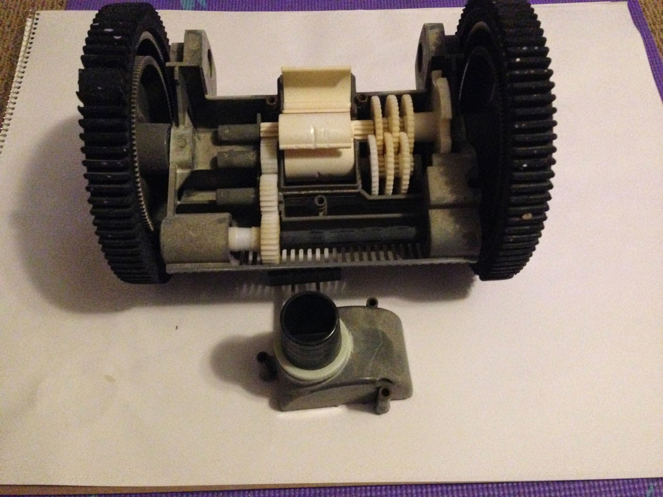
Both wheels need to be removed to expose the rod holding the turbine in place. Use the Allen wrench to remove the single screw holding each wheel to the cleaner.

The rod holding the turbine needs to be pushed though the pool cleaner.  This will be the most difficult part of the install. The rod will come out on the side with four small gears in a single line. Depending on the age of the unit, this rod might have rusted in place.

In this specific case, as shown a hammer and screwdriver were used to force the rod out of position, freeing the center turbine. Once the rod is out, the turbine can be pulled out of the cleaner.


A picture of the old and new turbines for comparison.

The new turbine is placed into the old turbine’s position with the flaps falling towards the front of the cleaner.

The rod now needs to be pushed into the cleaner from the opposite direction from which it was removed. When the rod gets to the turbine, the turbine will need to be held up to line up the rod with the turbine’s center hole.

This rod also holds the back 3 gears in place, so as the rod gets to each one, they will need to be held up in position for the rod to pass though them. Needle nose pliers can be used to help grab and hold these up one at a time.


To get the rod completely in, it was hammered back into place. Once it is fully inserted, the rod should not be visible when viewed from above.


Both wheels were reattached to the cleaner.


The center cone is placed back over the turbine (it will only fit on one way)

The top shell is placed back on the cleaner, and the three Phillips head screws are placed back in to secure it down.

Monday, October 27, 2014

Fix a Two-Wheel Pool Cleaner Gear


This will cover how to fix a two-wheel pool cleaner (by Pool Vergnuegen) where the wheels turns freely without moving the turbine. Written by us at Wine Country Pools in Temecula www.WCPandS.com. This is how we did this specific fix and not meant and a how to guide.

Parts used:
-Phillips head screwdriver
-Hex key or Allen wrench or Allen key
-Pool cleaner gear part # 896584000-471 (reduction gear)


Before opening the cleaner, check that this is not a wheel hub problem. See our previous post here on checking and replacing a wheel hub.

There are a set of four gears that turn the right wheel. If any one of these wear down from normal use, then the wheels disconnect from the main turbine. To determine which of these is bad, the cover first needs to be removed.

Locate and remove the three Phillips head screws directly on top of the pool cleaner.

After they have been removed, the top half shell of the cleaner can be pulled straight up and off of the cleaner body.

The center cone can also now be pulled straight up and off, exposing the turbine.

To free up some room inside the cleaner, the blades of the cleaner should be removed. Move the turbine around and when a blade is at the top, slide it out of its space.

Once all of the blades have been removed, inspect the gears in the unit.

The two gears that connect the turbine to the gear drive are the same model gear.
In this case, one looks different since one has been worn down.

To replace this gear, the pin holding it in needs to be removed. Using an Allen wrench from the inside (side with the turbine), tap the pin out.


With the pin moved over, the old gear can now be removed.

A comparison of the new and old gears is shown below.

Place the new gear in the old gear’s position. The Allen wrench will be used again to move the pin back in place.


A short video of the gears now moving when the wheels move.

The turbine blades need to be put back in. Note that the largest end connects directly to the turbine and they fold towards the front of the cleaner.


Place the cone back on the cleaner, lining up the three screws’ holes.

The top shell can now be placed back on the cleaner. (This will only fit in one direction.)


Friday, June 20, 2014

Replacing a swimming pool AMF Paragon Timer

This was written by us at Wine Country Pools & Supplies of Temecula California, our main site can be found here.
This write-up will cover replacing a broken AMF Paragon mechanical timer with a direct fit replacement “Multiple Controls Replacement” switch from Precision with manufacturer’s model number CD 104-PC.


The Paragon timer setup (especially the new replacement model) looks similar to the more common Intermatic mechanical timers, but they are not interchangeable. The housing fittings on the left side of the timers were made for one type of attachment and will not work on each other’s housing. 
Notice the different sizes of the metal "hooks" on the left side of each below.

The most common mechanical pool timer is the Intermatic T104M as shown below.
If you have an Intermatic time clock and want to see one replaced, our previous article doing just that can be found here.

Before starting this install, the main breakers for the pool equipment are turned off.

After confirming the power is off at the timer, the plastic cover over the exposed wires just under the old timer is removed.


Since this is a 220V setup, there are two power wires coming in with a single ground wire.

Note: Whoever had previously installed this time clock did not connect the ground to the timer; instead, it only passed though the box to the pump. This was a mistake on their part as every mechanical timer should have a ground wire connected directly to it.

Note: When moving the wires from the old timer to the new timer it is important to note that the order of wires is not the same. On the old timer the incoming hot wires are 1 and 4 and on the new timer they are 1 and 3.

Each wire is held in with a single screw. Once loosened with a Phillips-head screwdriver, the wire can be pulled out of the old timer and into the new timer.


To remove the old timer, on the far right is a metal clip.
This is pushed to the right, away from the clock. Now the right side of the timer can be pulled forward. The left side is sitting in two grooves that will pull out as the right side is moved forward.

To insert the new timer in the old housing, on the left side of the timer are two metal ends that will fit into two holes on the old housing. Line these up and push the timer into them.

Once the left side is in, the right side is pushed back in, locking the timer into place.

An extra piece of wire is used to connect the time lock to the ground wire.

After all wires are transferred over and the new clock is in place, the plastic cover that came with the clock is placed over the exposed wires.

The on and off switches are attached to the dial to the desired times.

The power is turned on at the breakers and the timer is tested.