What this is about
This write-up will cover the CPSC Series Salt water chlorine generator (CPSC24) manufactured by Compu Pool Products. This article was written by www.WCPandS.com
This was only the 2nd or 3rd CPSC salt generator I have seen in our area. The most common type found in this area (Southern California) is Hayward, Pentair and Jandy. The job was to replace an older, non-working CPSC with a new CPSC generator and power supply.
Note: The CPSC model line is very similar to the Eco Matic salt water chlorine generators.
The previous cell:
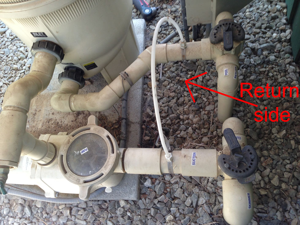
This was a replacement of one CPSC24 for a new CPSC24, so the plumbing and mounting of the power supply was already done by someone else.
The old unit pictured below cracked when the cell blades came loose and pushed through the cell casing, allowing water to leak out.

I don’t know if the old power supply still worked since it had already been disconnected by a previous pool man, but it will also be changed out with a new unit.
Unboxing the new unit:
This package contained everything needed except for the PVC pipe and fittings needed to connect a cell to a system that didn’t already have one.

Box contains:
-User manual
-Outer cell casing
-Main cell unit
-Power supply
-Power supply mounting bracket
-Screws to hold mounting bracket
-2 two inch pipe unions
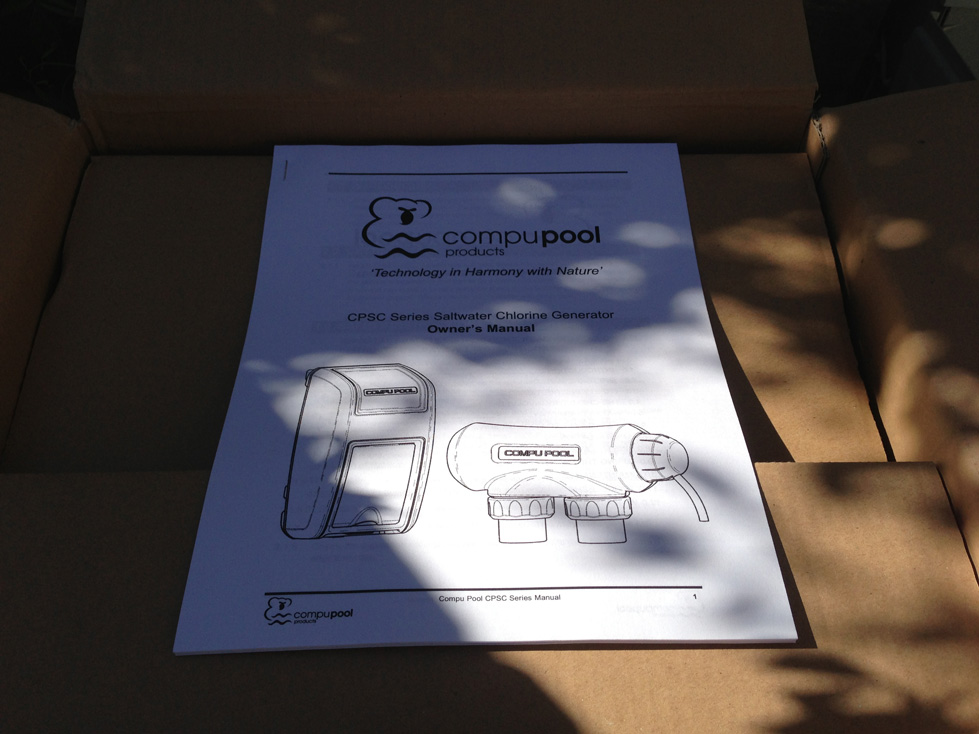


What sets this type of salt generator apart from the more commonly found models (Hayward, Pantair, Jandy) is that the pipes connect to the cell perpendicular to the cell instead of parallel to it.

This seems to be helpful when dealing with a space that appears too small to have a cell plumbed into it. However, I would be curious to know if anyone has measured a greater drop of water flow due to pipe restrictions using this system as compared to the parallel connecting type.
The Power supply included a power cable that is wired directly to the power source (most likely a mechanical timer or relay switch, depending on your situation) This is a nice change from having to buy your own wire and conduit (To view an example of using your own wire see Hayward install here (link)) but having this premade cable is a disadvantage when the distance from the cell to the power supply is longer than the supplied power cable.
Installing the new unit:
All power was turned off at the breakers.

On the back of the cell where the power cable connects is a rubber plug that can be pulled back and off exposing the 3 connecting wires. (This one did not have the clear dome the updated version does)These colored wires can now be pulled out.

Because this is a new CPSC replacing an older CPSC the two unions were unscrewed and then the unit was placed on top and screwed on.


The new unit has a clear dome that covers the 3 connecting wires with a plastic nut that secures it to the cell.


On the top near the back of the old power supply were two screws securing it to the wall. Once these are removed the power supply could be pulled out and off then the new power unit will fit in its previous place secured by the same two screws.


To connect the power use the two hanging wires at the end of the free cable coming out of the new power supply and connect them directly to the pump power. A few examples of what this could be are a mechanical timer or an automatic controller relay. In this specific example it was an automatic controller relay.
Note: The salt cell should go on and off with the main pool pump.


Clean up and put things away the installation is finished


Issues with new unit:
A week after the install was complete I noticed the connecting end where the 3 wires joined to the cell had started to burn and melt.


The pool system was immediately turned off and the power lines were disconnected between the salt system power supply and the pool equipment.
I don’t know how long the wires had been overheating, but from a quick Internet search I was able to find other CPSC units with the same issue that were in worse shape than this one.

After contacting Compu Pool support a new replacement salt cell generator and power supply were sent out under warranty. The damage to the burnt cell did not cause leaks when the main pump was running, so while waiting for the replacement the pool system was left on to filter normally.
The day the replacement unit arrived it was immediately installed and the old unit sent back.
There have been no further issues with this new unit.
Final thoughts:
There are a few advantages to using the CPSC system, including needing a smaller area to install the cell into it, the unit included a premade power line and this leads to an overall ease of installation. The cell generates chlorine just as well as other similar sized salt cell generators.
I don’t know how common it is for these CPSC units to overheat and only found two other examples of this happening online. At least for now I would not hold this specific issue against them. However, given the choice during a new install I would not pick the CPSC line. Since these are not commonly found in this area all of the parts had to be special ordered. The Compu Pool customer support was helpful, but I got the feeling when I communicated with them that they were a small company and this could be an issue with future dealings with them. Also, I have some doubts about the perpendicular connections to the cell as it relates to water flow.