Tuesday, June 28, 2016

Piranha Power Pole Replacement kit


Piranha Power Pole Replacement kit
This is a write up of the Power Pole Replacement kit (Manufacturer part number PP-LV-G). The Power Pole is currently my main pole since the end has two sets connection slots. This is usually a problem area (the attachment tools eventually breakdown the connectors) so having a second set helps to extend the life of the pole.
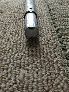
As with any swimming pool pole certain parts seem to ware out so the makers of the Power Pole released a pack of the most common fixes to their pole. In this specific case the rubber handle on the end of my pole finally wore down and fell off. This kit came with more then just the handle (Lever springs and internal stopper) and all but one was used in this writeup.


Since my poles handle had already fallen off I did not need to remove anything to start.
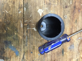
The new handle just slides on, note that the inside is not perfectly round, and there is a flat side that lines up with the flat side of the pole.
Once on the screws are inserted and tightened.
Note: Originally the screws on mine fell out before the handles end was worn down. So I added some gorilla glue to the screws before inserting them. (I assemble this kit about 6 months ago and this worked out well as the screws are still in their correct place)

The inside pole is supposed to stop from before being fully removed from the outer pole via a internal stopper. The kit comes with a replacement internal stopper, mine was in good condition yet I still replaced it since it was included. With the handle off, the inner pole is pushed down and out through the bottom of the outer pole to view the old stopper.
The the old stopper was removed and the new set in its place.


If your poles internal spring breaks this kit does come with a replacement that looks like it would be easy to replace (instructions were on the box). I did not replace the lever spring since I didn’t see the point. On the past Power Pole I had there was never a problem with the lever, it was the center pole holes there were becoming egg shaped that was the problem. 


As seen in the picture below this poles hole are starting to become egg shaped.

If you have a Power pole with either the handle, the lever spring or the center pole pulls out of the top of the outer pole this kit will fix those. But if your center pole holes are becoming egg shaped causing the inner pole to slip out of the locked positions this kit will not help with that.

Monday, February 8, 2016

Hayward TriStar Motor Replacement

Hayward Tri-Star Motor Replacement

This was a motor replacement for a Hayward Tristar 2 speed motor done by us at Wine Country Pools and Supplies. This is not meant as a how to guide; it will show you how this specific motor was replaced.

Parts needed:
Replacement motor
9/16 Socket wrench
1/2 Socket wrench
Square bit?
3/16 Allen wrench
PS-3890 Pump Seal
ALA-601-5506 Volute O-ring
SPX3200T Housing O-ring
Phillips head screw driver
Flat head screw driver


Start:
All breakers to the pool equipment are turned off.

The pump is connected to the plumbing system by two quick release unions.
Removing both of these allows the motor to be moved.


The motor can now be moved, and the backside can be accessed to remove the electrical wires, freeing the motor.

Note: the grounding wire connected to this motor was removed with a flat head screwdriver but it is not shown in the photos.

At the back of the motor, the rear cover can be removed by first removing the two flat head screws, then pulling the plastic cover away from the motor.


There are three hot power lines. One is shared (tan), one for low speed (blue), and one for high speed (blue red). The power wires were already marked on this motor by the installer. The green is the ground wire. All the wires need to be disconnected.

The conduit elbow needs to be loosened so the wires can be pulled out of the motor.
(No picture)
To separate the front of the pump from the motor, a ½ inch wrench was used to remove the 6 bolts (3 on each side).


The two halves can now be pulled apart.


To remove the volute, two square head screws were removed. The volute can now be pulled off, and away from the motor.

The impeller ring can be pulled off. Make a note of the side that the raised edge faces.


To remove the impeller, first the center screw needs to be removed. A 3/16 Allen wrench was used. This is a reverse thread screw.

To unscrew the impeller, the motor shaft needs to be held in place. A wrench was used to hold it in place from the back.

Then the impeller can be unscrewed and removed.

To remove the motor from the seal plate, 4 9/16 bolts needed to be removed from the back of the seal plate.


Now the seal plate can be pulled forward away from the motor.

On the seal plate, the old seal was removed with a flat head screwdriver, pushing it out from the backside.

The new motor and the old seal plate are reconnected with the 4 9/16 bolts.

The new half seal (PS-3890) (the larger half) is inserted with the metal side facing the inside of the seal plate. A flathead screwdriver was used to push it into place.


On the impeller, the old seal needs to be removed using a flathead screwdriver. Now the new smaller seal piece is inserted into the impeller, with the rubber side facing the impeller.
(No picture)

To tighten the impeller to the motor, the shaft needs to be held again from the back of the motor. While holding the shaft in place, the impeller can be screwed back on to the motor with the new seals already in place.


The center screw needs to be reinserted into the impeller using the Allen wrench. Note again this is a reverse threaded screw.


The impeller ring was reattached, paying attention to the correct side of the raised section.

The volute was reattached using the two small square bolts.


The new volute O-ring can be attached.

The new seal plate gasket is set into the seal plate.
The front of the pump and the motor can be reconnected.  They are first pushed together, and then the 6 1/2 bolts are reinserted to hold them together.

To connect the conduit elbow, a plastic screw needed to be removed.


Once the pump was put back together, it needed to be rewired using the new motor diagram. The motor didn’t list high, low, and common on the backside like the previous motor, but did have a diagram on the side.


Unions and grounding wire were reconnected.


The breakers were turned back on and the system was back up and running.